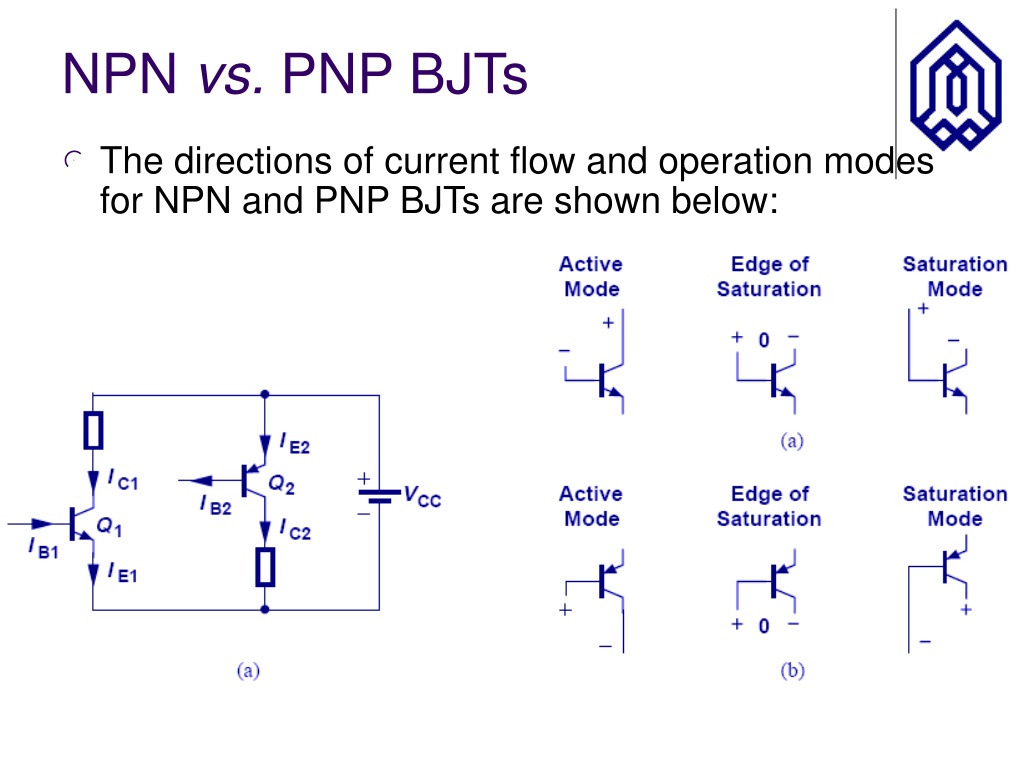
Instead, manufacturers include an NPN or a PNP transistor to handle higher currents at a sensor’s output. The measurement circuits do not directly send a high-current signal (a few 10s of milliamperes) to a controller.

In a Hall-effect position sensor or an ultrasonic distance sensor, for example, sensitive circuits detect a magnetic field or a distance. This type of current “amplification” finds use in many sensors. This circuit is equivalent to a current-source because it controls the flow of current from the highest potential to the load that connects directly to ground. This circuit shows how current drawn from a PNP transistor base controls the flow of current from the emitter to the collector. (The current goes to ground.) A small current out of the base causes a larger current to flow from the emitter to the collector.įigure 11. To control the LED brightness we draw current from the transistor base. Figure 11 shows an LED-control circuit with a PNP transistor. But in PNP transistors the control current flows out of the base rather than into it. PNP transistors work in a similar way: The base current still determines how much current flows from the emitter to the collector. Think of this circuit as a current sink because the LED connects directly to the higher potential and the transistor connects directly to ground. A higher current into the base lets a higher current flow and the LED becomes brighter. A small current into the base turns on the transistor just a bit. An NPN transistor controls current flow through an LED. Small changes in base current cause larger changes in the collector-to-emitter current.įigure 10.

The combined base and collector currents flow out the emitter terminal. When a small current flows into the base the transistor starts to conduct a larger current from the collector through to the emitter and then to ground. In this circuit, current will flow from the positive supply through the LED into the collector and then out the emitter to ground. Figure 10 shows a circuit for a common NPN-transistor that connects to an LED. The transistor base connection controls the amount of current that flows. Schematic-diagram symbols for an NPN and a PNP transistor.īoth transistor types operate as current devices, so think of them as valves for current flow.

The arrow’s direction identifies the transistor type in data sheets and schematic diagrams.įigure 9. The arrow points out for an NPN transistor and in for a PNP transistor. In circuit diagrams, the emitter always appears as an arrow. NPN and PNP transistors each have three leads, a collector, a base, and an emitter, as shown in Figure 9. Before discussing sensors and controller outputs, a short explanation of both transistor types will get you off to a good start without the need for a degree in semiconductor physics! (The Ps and Ns refer to types of semiconductor material.) PNP?Ī: The initials indicate a type of transistor used in the output section of many sensors. What do these abbreviations mean and what are the differences between NPN vs.

Some of the sensors I plan to use come in two varieties, PNP and NPN. Q: Now I understand relays and current sinks and sources. In the first two installments, Jon covered relays and sink vs. In the third installment of this five-part series, Jon Titus explores the basic elements of a control system.


 0 kommentar(er)
